
Open media
If you did not configure Wi-Fi during the initial firmware upload, or if you need to update the device's current Wi-Fi credentials, you can quickly make these changes by returning to the firmware upload page.
Simply enter the new network details in the form, check the Initialize only box, and click "Create device." The device configuration will update immediately without reinstalling the firmware.
If you cannot use the Web Installer, or if you require advanced configuration, you can use one of the following two methods to configure and control your HomeGenie Mini device:
This guide will walk you through both methods.
Upon first power-up, your device is not connected to any network. The status LED will blink continuously to indicate this. Use one of the following methods to establish a Wi-Fi connection.
While the video demonstrates this process on an ESP32-S3-CAM, these steps apply to any ESP device running the HomeGenie Mini firmware.
If WPS is not available or you prefer a manual setup, you can use the HomeGenie Panel app.
The status LED provides key information about the device's state:
| LED Pattern | Meaning |
|---|---|
| Continuous Blink | Not connected to a Wi-Fi network. |
| Solid On | Actively attempting to connect (WPS/Wi-Fi). |
| Slow, Steady Pulse | Successfully connected to Wi-Fi. |
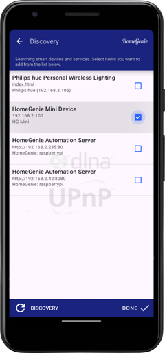
Once connected to your network, the device will appear in the discovery list within the HomeGenie Panel app. Simply select it and tap "Done" to add it to your dashboard.
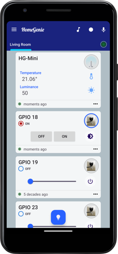
The modules and controls available on your dashboard will depend on the specific firmware version installed. For example, the smart-sensor-d1-mini firmware provides access to temperature and light sensors, along with 2 configurable GPIO switches.
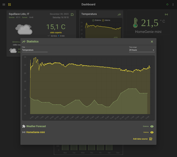
HomeGenie Mini devices can be easily integrated into a HomeGenie Server instance, following a few simple steps as demonstrated in the video below. The video shows the process for connecting a HomeGenie Mini Smart Camera to HomeGenie Server to leverage its advanced capabilities, but the procedure is identical for all HG-Mini device types and firmwares.
Connecting your HG-Mini to a HomeGenie Server unlocks powerful features. The server acts as a central hub, providing long-term data logging and advanced visualization capabilities far beyond the device's local storage or the Panel app's immediate view. You can create complex automation routines involving the HG-Mini and other devices managed by the server, utilize its more powerful data processing for analysis or complex event triggering, and access your HG-Mini's data and controls as part of a unified system dashboard. This integration elevates the HG-Mini from a standalone device to a fully integrated component of a larger smart ecosystem managed by HomeGenie Server.
For advanced users, HomeGenie Mini can be configured directly through a serial terminal (e.g., via a USB connection). The command-line interface accepts two types of commands:
# prefix: Used for system-level commands (e.g., #RESET)./api/ prefix: Used for any standard API command (see the Device API page).Connect to your device's serial port using a terminal emulator (e.g., PuTTY, Serial Monitor) with a baud rate of 115200.
The following system commands are available:
| Command | Description |
|---|---|
#RESET | Restarts the device. Necessary to apply some settings. |
#WPS | Manually triggers the WPS pairing mode. |
#UPTIME | Shows how long the device has been running. |
#VERSION | Displays the current firmware version. |
These commands are used to configure the most fundamental settings of your device. These are typically set once during the initial setup and control the device's identity on the network, its Wi-Fi credentials, and its time synchronization settings.
#CONFIG:device-name <name>Sets the friendly name for the device. This name will be used to identify the device in the HomeGenie Panel and on the network (as its hostname).
<name>: The desired name for your device. The name should not contain spaces, as it is also used as the network hostname. Use hyphens or underscores instead of spaces.Example:
#CONFIG:device-name Living Room Sensor
#CONFIG:wifi-ssid <ssid>Sets the SSID (name) of the Wi-Fi network the device should connect to.
<ssid>: The name of your Wi-Fi network. This is case-sensitive. Note that this command does not support SSIDs that contain spaces. For such networks, please use the HomeGenie Panel app for the initial configuration.Example:
#CONFIG:wifi-ssid MyHomeNetwork
#CONFIG:wifi-password <passwd>Sets the password for the specified Wi-Fi network.
<passwd>: The Wi-Fi password. All characters entered after #CONFIG:wifi-password (including spaces and special characters) will be treated as part of the password.Example:
#CONFIG:wifi-password my_S3cur3/P@ssw0rd!
#CONFIG:system-ntp-server <server_address>Configures a custom NTP (Network Time Protocol) server for time synchronization. This is optional; the device uses a default server if this is not specified.
<server_address>: The domain name or IP address of the NTP server.Example:
#CONFIG:system-ntp-server pool.ntp.org
These settings allow you to manually set the time or configure how the device synchronizes its clock automatically.
#CONFIG:system-time <hh>:<mm>:<ss>.<ms>Manually sets the system's internal clock. This is useful in environments where an NTP server is not accessible. The time is specified in 24-hour format.
<hh>:<mm>:<ss>.<ms>: The exact time, including hours, minutes, seconds, and milliseconds.Example:
#CONFIG:system-time 14:30:00.000
#CONFIG:system-zone-id <zone_id>Sets the timezone using a standard TZ Database name. This is the recommended method for time configuration as it allows the device to automatically handle daylight saving time changes.
<zone_id>: A standard Olson timezone identifier (e.g., Europe/Rome, America/New_York). A list of valid identifiers can be found on Wikipedia.Example:
#CONFIG:system-zone-id Europe/Rome
#CONFIG:system-zone-offset <tz_offset>Manually sets the time offset from UTC in hours. This is a simpler alternative to zone-id but it does not automatically handle daylight saving time.
<tz_offset>: The offset from UTC, expressed in hours (e.g., +1, -5).Example:
#CONFIG:system-zone-offset +1
These commands are used to read and write specific configuration parameters from the device's memory.
| Key | Description | Default |
|---|---|---|
sys-rb-n | GPIO pin number for the factory reset button. | -1 (disabled) |
sys-sl-n | GPIO pin number for the system status LED. | -1 (disabled) |
io-typ01 | Channel 1 Type. Can be: Switch, Light, or Dimmer. | (empty) |
io-pin01 | Channel 1 GPIO pin number. | -1 (disabled) |
io-typ02 | Channel 2 Type. | (empty) |
io-pin02 | Channel 2 GPIO pin number. | -1 (disabled) |
| ... | (channels 3 through 8 follow the same pattern) | ... |
Example 1: Setting parameters
To configure the status LED on GPIO 10 and the reset button on GPIO 0, then apply the changes:
Assign GPIO 10 to the status LED
#SET:sys-sl-n 10
Assign GPIO 0 to the reset button
#SET:sys-rb-n 0
Restart the device to apply changes
#RESET
Example 2: Getting a parameter value
To check the current GPIO assigned to the status LED:
#GET:sys-sl-n
The device will respond with the current value:
#GET:sys-sl-n=10
